Design of geosynthetic mattress underneath embankment on top of piles (∼following BS8006-1)
Piled embankment using geosynthetic mattresses
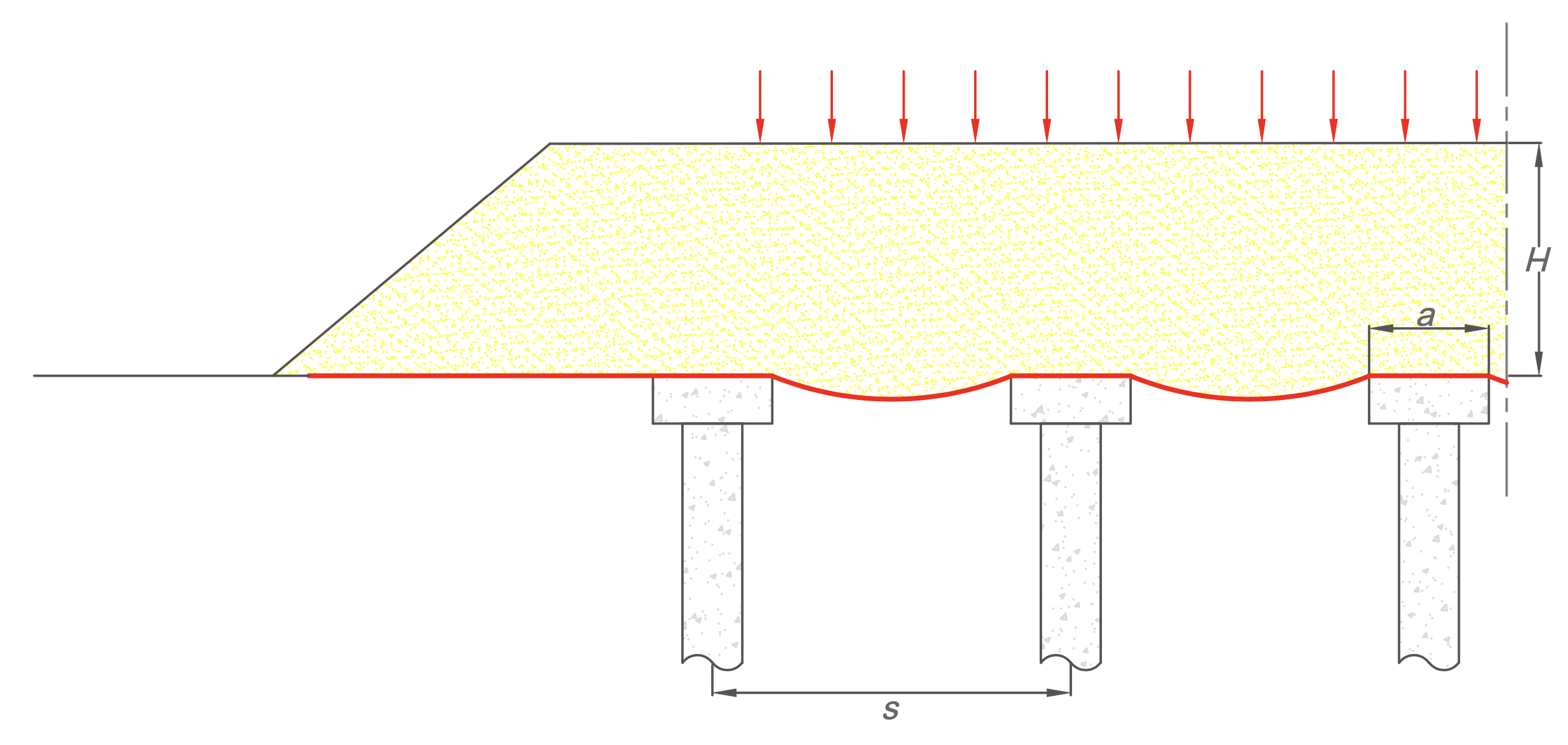
Infrastructure works on low-bearing ground are a frequently occurring challenge. If the subsoil does not have sufficient bearing capacity to support the embankment to be build on it, additional support will be necessary. You can make the construction of the embankments possible, by means of piles together with a mattress. A mattress on piles uses the natural arching principle in soil. The forces from the ground and the top load are transferred to the piles via concentric circles. The soil under these circles is supported by the geosynthetic together with the underlying soil. This calculation module approaches BS8006 (British Standard) as closely as possible, based on the hypothesis that the underlying soil has no bearing capacity at all.
Pile cover
To increase the support of the piles, a concrete lid is placed on top. Typical dimensions of the pile cover are 0.75 x 0.75 x 0.45m. Because the surface of the cover is larger than the pile head, the distance to be bridged in between the piles decreases.
Granulate mattress
A strong and stiff (high E-modulus) geotextile or geogrid is tightly rolled out over the pile covers, the typical size of the standard rolls is 5m x 100m. This requires a sophisticated laying plan, because the final width of the rolls and positioning must be chosen in such a way that sufficient anchoring due to friction will occur after filling/loading. Because the geosynthetic material has a limited width and therefore no continuous strength in the transverse direction, a second layer of geosynthetics will be rolled out at right angles to the first layer. These two layers come into contact with each other, alternatively a layer of granulates, to be compacted, is placed in between.
Reference
British Standard, BS8006-1, 2010. Code of Practice for Strengthened/Reinforced Soils and Other Fills, ISBN 978 0 580 53842 1.