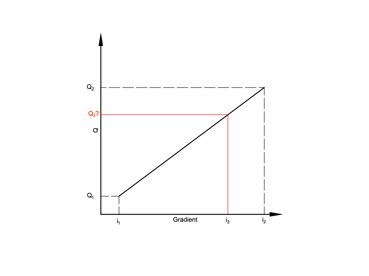
Drainage capacity of a geocomposite under a given gradient by interpolation
Capacity for drainage geocomposite (GCD) on a slope
The minimum drainage capacity requirements for a drainage geocomposite (GCD) are calculated for the conditions of (1) the slope angle (β), (2) the normal component of the load (e.g. saturated soil layer) and (3) the inflow of water through the soil layer. The in-plane transmissivity of the soil layer itself is not taken into account for calculation of the total drainage capacity, but can be considered as an additional safety factor in case its permeability coefficient (k) is relatively high (e.g. sandy soil).
Texions’ drainage geocomposites (GCD’s) have a high in-plane transmissivity. The transversally permeable drainage geocomposite consists of an in-plane drainage core made from a three-dimensional structure (jumbled structure of threads, a geonet, a cuspated structure) with a geotextile filter fabric (GTX) attached to one or to both sides. When installed on a slope on an impermeable geomembrane (GMB), the drainage geocomposite is placed underneath the reinforcement geogrid (or geotextile).
The hydraulic gradient (HG)
The hydraulic gradient (HG) is the height of water (head height H) divided by the horizontally measured distance (l) between the points where the highest and lowest heads on the drainage geocomposite (GCD) are considered. Therefore HG = 0.1 for example means a head height of 3m with a GCD horizontally projected distance of 30m. A 45° slope is the equivalent to a HG = 1.0, so the HG is the Tan(β) of the slope angle and as the head height increases, it is possible to get HG's above 1. The way to calculate the slope from the HG is to use the inverse Tan of the HG (Tan-1 as it is on most calculators), e.g. Tan-1 (1.0) = 450, Tan-1 (0.5) = 26.60, Tan-1 (0.1) = 5.7°.
Calculations for specific projects
First, in the Texion module 'Drainage capacity under a soil layer', the minimum required flow rate (l/m/s) is calculated. On the technical data sheets of the products, the drainage capacity is generally given at a gradient (i) = 1 and = 0.1 because this is indicated in the test standards. A gradient 1 means h = 1 and x = 1, so an angle of 45 ° with the horizontal. The drainage capacity changes as the load increases (or decreases) above the 3D geocomposite. The technical specifications give values for example 20, 100, 200 kPa.
The situations of the specific project do not generally correspond to the information given in the technical data sheets of the products, but to values in between. For example, a drainage capacity under a gradient i = 0.3 and a load of 120 kPa. The flow rate value for these precise cases is calculated by applying an interpolation, this is allowed because the curve of the measurement results (Q versus P) is linear.
Using the calculation module to calculate the flow rate under a given slope
Enter the smallest and largest known (measured) value of drainage capacity (l/m/s) under the corresponding gradients i. Then enter the slope gradient of the project, the result of this calculation gives the drainage flow rate (Q).
Generally it will be necessary to calculate first the interpolation under the overlying load and then under that of the gradient i.