Geotextile reinforced embankment - Method P. Risseeuw
Geosynthetic reinforced embankment
Embankments are designed against the threat of collapsing. Three types of failure are distinguished: - external - internal - squeezing
Each of these mechanisms applies a calculation method. In case of insufficient strength of the soil, reinforcement by geosynthetics is used. The methods will be illustrated one by one.
External failure
Embankments are vulnerable to failure along slip surfaces. Such a risk is investigated by so called 'stability programmes'. The driving and resisting moments are determined. Their ratio is called factor of safety. Numerous programmes are available. If the safety is insufficient a geosynthetic may be applied. In case of failure a tensile force is generated, which increases the resisting moment. Thus, a required factor of safety is obtained. Most of the stability programmes facilitate the use of geosynthetic in a design. In the preliminary phase of a design it is often useful to make simple assessments of the need of geosynthetic. A tool for this purpose is offered in this Applet. The methodology is introduced by P. Risseeuw.
Approach
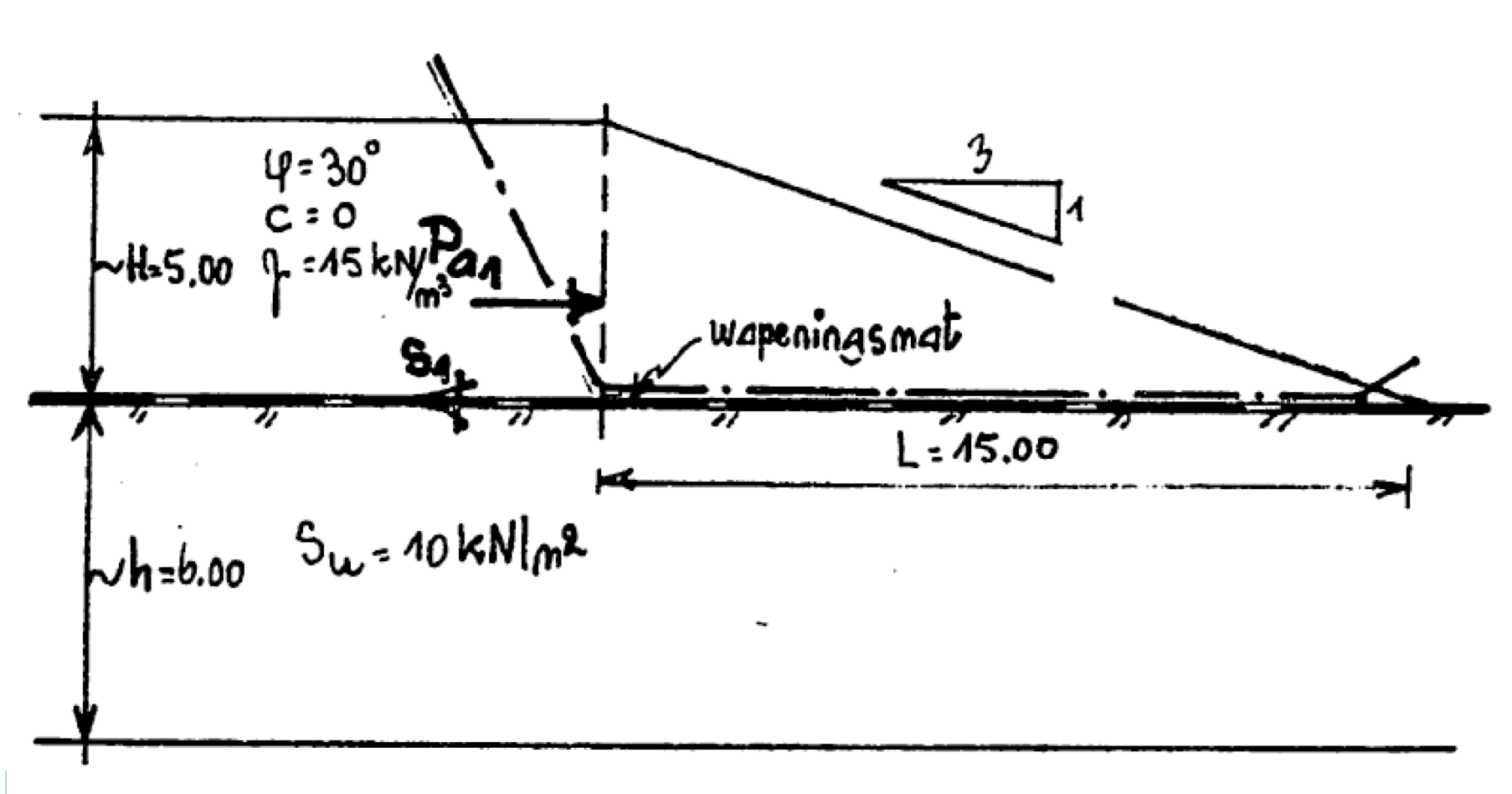
An outline of the geometry is shown in Fig. 1. The subsoil is drawn brownish, the embankment yellowish. Dimensions are indicated by symbols. The slip plane has a circular shape. Along this plane shear stresses act: in the subsoil the undrained shear strength and in the embankment an effective value. This last shear stress depends on the material of the embankment and the condition at point D. In case of a friction material the angle of friction plays a role, in case of a cohesive material the cohesion. Often the embankment is cracked at point D. It is the responsibility of the user to assess an effective value for τa. The weight of the embankment is determined by the unit weight γa. A total stress approach is applied.
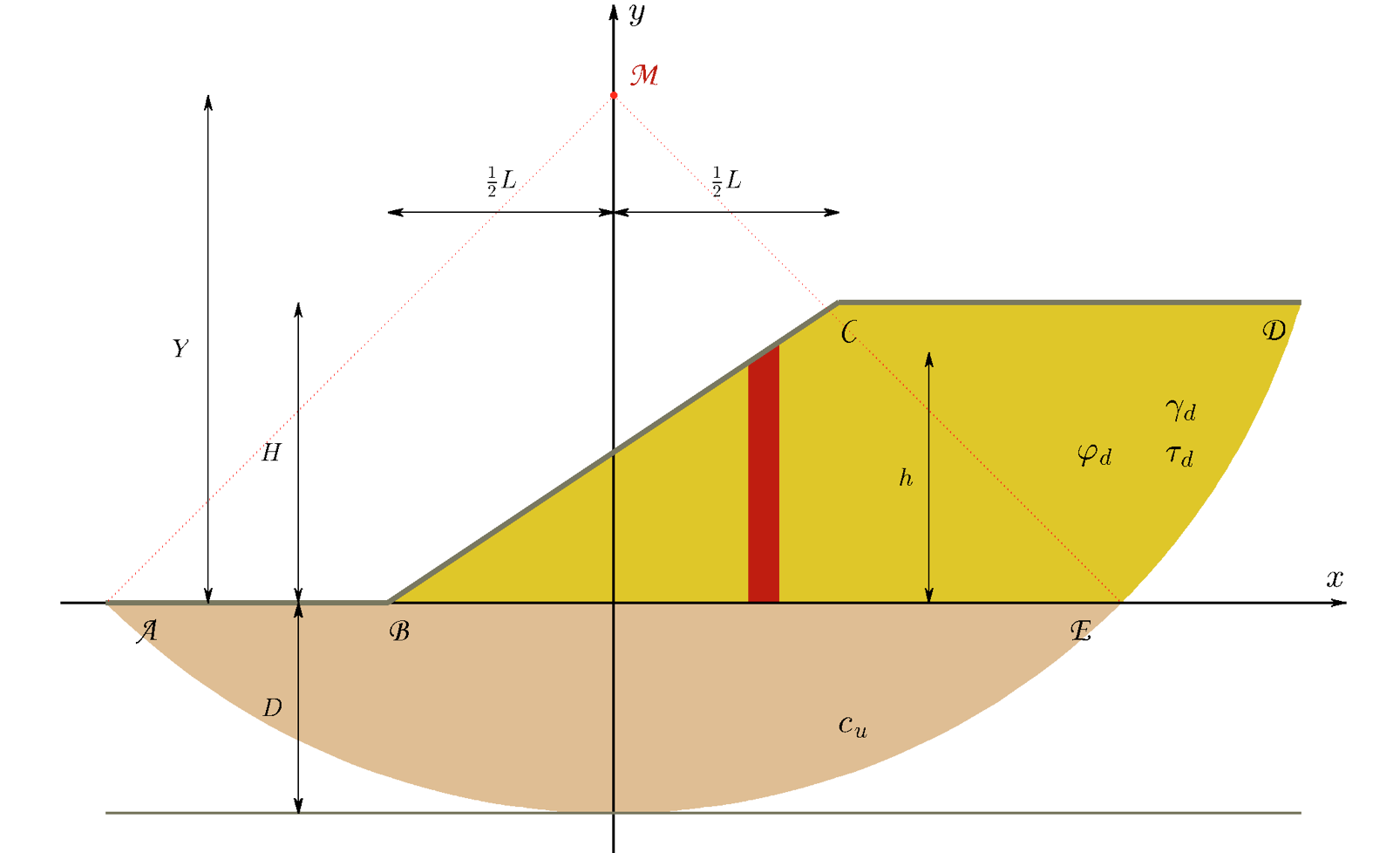
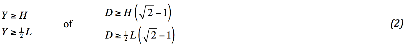
In stability computations the slip plane is determined with the lowest factor of safety. Usually, this is performed by computer. Risseeuw has empirically assessed the position of the slip plane. He states, that the middle point of the circle is located straight above the midst of the slope, that the angle AME amounts 90˚ and that the radius of the circle is such, that the bed rock is hit. By formula:

For very thin subsoils this approach is less realistic. The stability methodology only works well for extending circles, which is the case if Y > H. To avoid complications during the mathematical formulation, it would be helpful, if point E is located at the right side of point C . The following is required:
This is not unfair.
Elaboration
The factor of safety is expressed as ratio of driving and resisting moment. In the current approach the driving moment is supplied by the weight of the embankment. The weight of the subsoil cancels out. The radius of the slip plane is Y √2 . The resisting moment consists of three contributions: the undrained shear strength along the first quarter slip circle, the shear stress along the rest of the circle and the tensile force in the geotextile S. By formula:
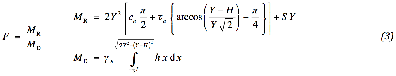
The height in the driving moment is determined by Fig. 1. A closed solution is found for the integrals. The integral limits are mentioned in bar notation.
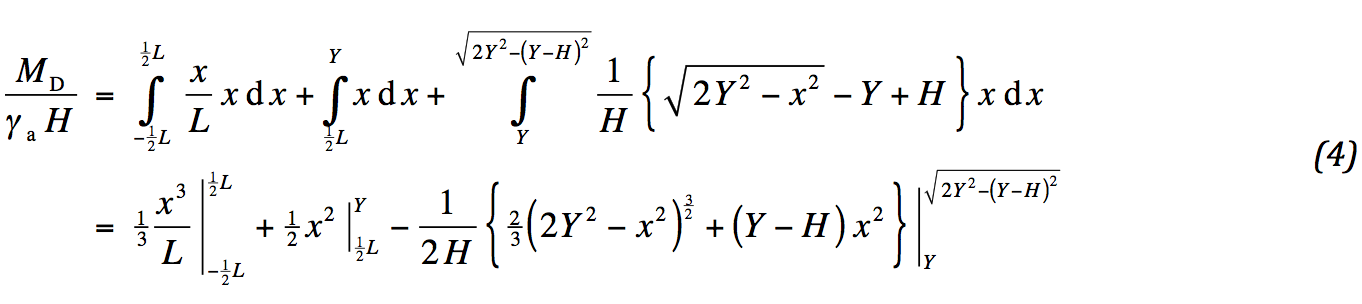
Substitution of the limits results in:
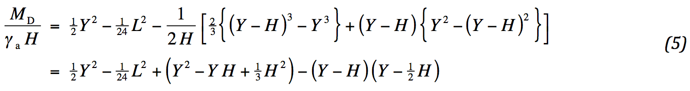
Substitution of the limits results in:

Thus the required tensile strength of the geotextile is determined for a desired factor of safety. From (3) and (6) it follows:
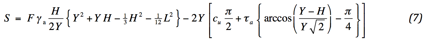
There is no need for a geosynthetic, if the result of (7) is negative.
Internal failure
A slope consisting of granular material is stable until its angle reaches the angle of internal friction. In the corresponding stress state shear stresses develop along a horizontal plane. By implication, the subsoil must withstand these shear stresses. To this end, the undrained shear strength must be sufficient.
If this is not the case, a geosynthetic might be applied to overcome the difference. It is not easy to determine the required strength. The stress state around the slope is complicated. Slope and friction along the geotextile play a role amongst others. Moreover, the transfer of stresses to the subsoil is complicating.
Therefore, Risseeuw has investigated the problem from a different conservative point of view. In the midst of the embankment the so-called active horizontal soil pressure is active. This pressure must be in one way or another transferred to the subsoil. If it is assumed that the friction along the geotextile is able to compensate the active pressure, it is sufficient to require that the geotextile is as strong as the active pressure. By formula:

A safety factor is added. Slope and undrained shear strength are not incorporated. It is altogether possible that in case of a small slope or high shear strength no geotextile is required. Therefore, the formula is conservative. Also, friction along the geotextile does not play a role. This means an uncertainty that the entire active pressure could be transferred.
In Fig.2 an outline of Risseeuw’s approach is shown. Here, at the same time an example case is demonstrated.
Squeezing
Squeezing is the process of loss of stability of the subsoil below the slope. The principle is outlined in Fig. 3. Four horizontal forces are acting on the hatched soil mass, two fixed normal forces and two limited shear forces. At the left side an active force is present with respect to the vertical force, at the right side a passive one. Both vertical forces are due to the dead weight. The balance of forces requires an upper limit for the active force at the left:
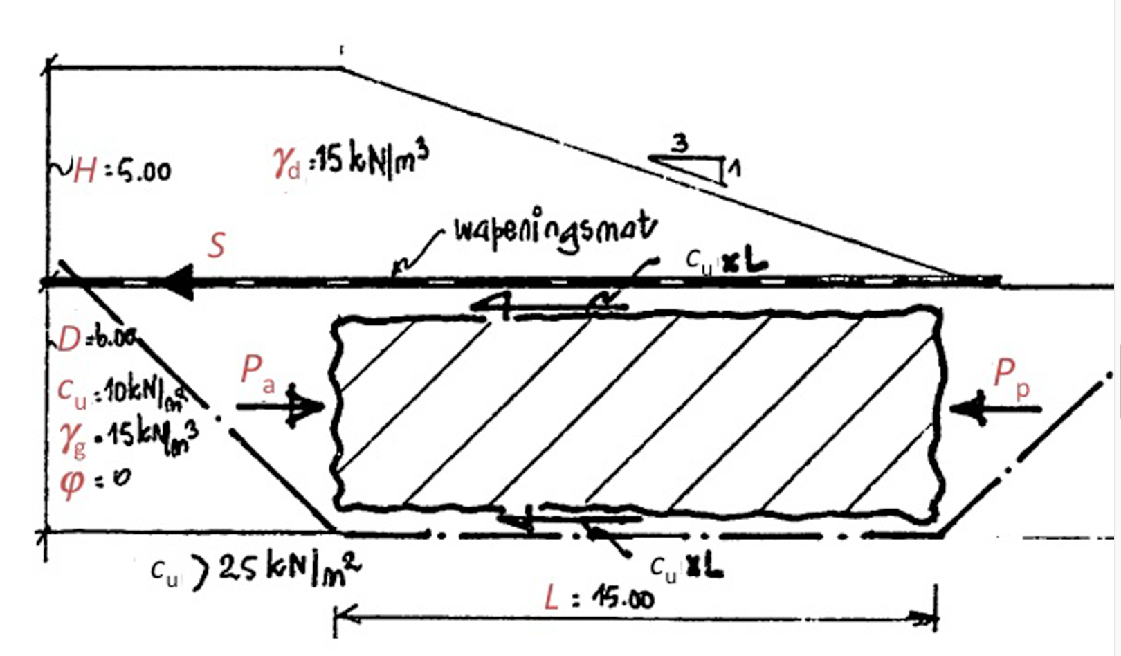
In Fig.3: an outline of the embankment with assessment of squeezing

For cohesive material the active stress is twice the value of the cohesion smaller than the corresponding vertical stress. The passive stress is twice the value of the cohesion higher. This leads to the following condition for the height of the embankment:

The shear stress at the top of the hatched soil mass is provided by the geotextile. The required strength is:

A safety factor is added.
Required strength geosynthetics
Three principles are discussed to ensure the stability of an embankment. For each principle the required strength is determined at the location of maximum effect. In general these locations will not coincide. No information is available to obtain a weighted assessment of the effect of all principles as a whole. Therefore, a conservative approach is adopted by adding all required strengths together. A safety factor is provided to each of the studied mechanisms. A weighted value for all is feasible. To this end, the introduced factors are partly related to the uncertainty in the soil and the model. For maximum flexibility indices are added: E for ‘external’, I for ‘internal’ en S for ‘squeezing’. Besides, for all mechanisms partial safety factors are set aside for the geotextile alone. Thus, the combined required strength reads:
The indices for the partial safety factors for the geotextile refer to i for ‘installation’, d for ‘durability’ and c for ‘creep’. During a calculation a few exceptions may occur. They are:

The 3 failure mechanism will not cause failure all together at the same moment, therefore the worst case is considered for the external failure and the internal failure, or (not and) the squeezing.
References
Risseeuw, P., “Rekenen met kunststof wapeningsmatten in en onder grondlichamen”, 1982.