Design of geotextiles applied in paved roads - Method Semmmeijer
Use of geotextiles
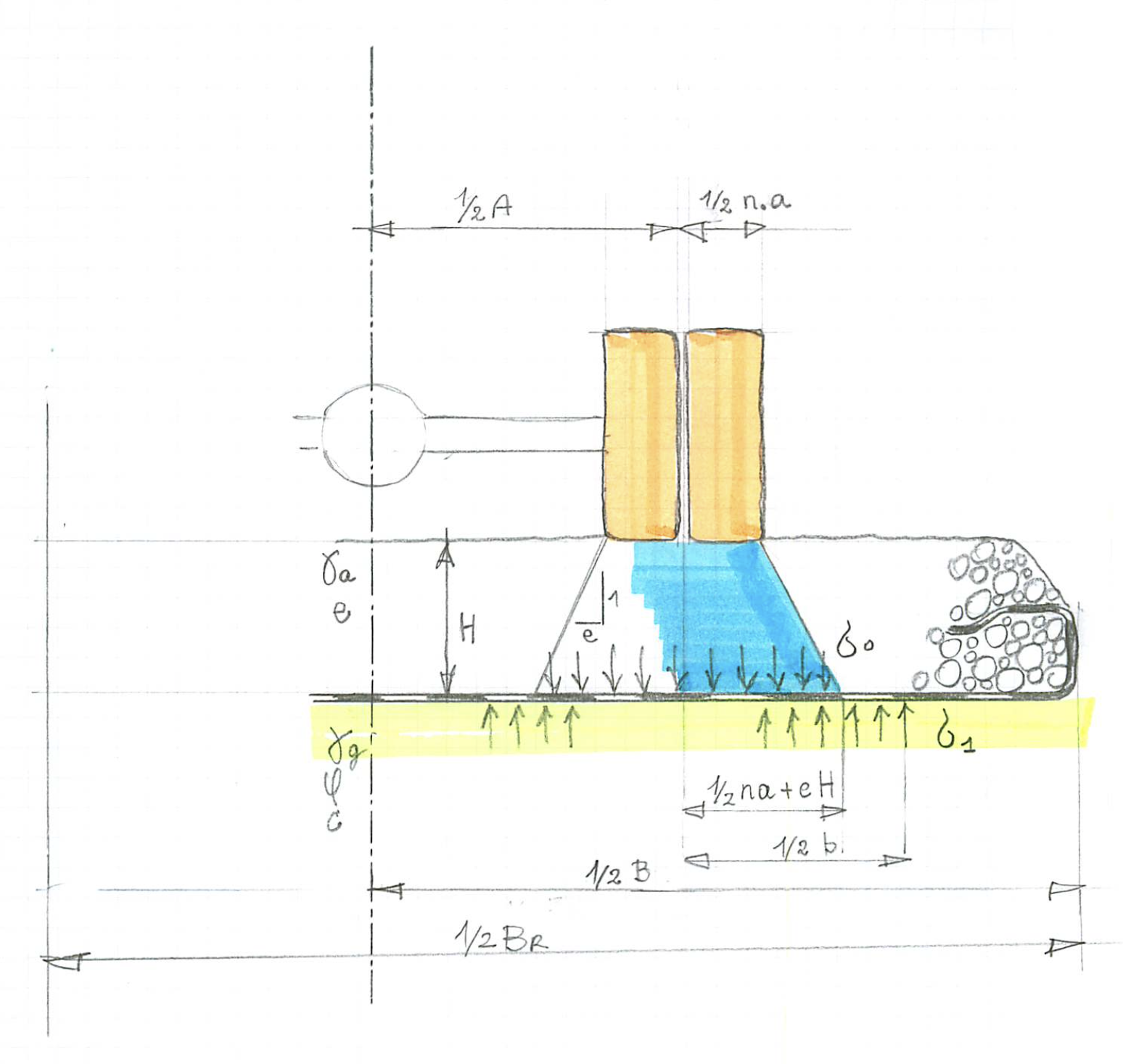
The application of geotextiles in road construction is interesting, if the bearing capacity of the subsoil is insufficient. The traffic load impends to collapse together with a part of the road. A geotextile will distribute the load over a wider area of the subsoil, thus, assuring equilibrium. Fig. 1 shows this principle. The traffic load is applied via the wheels of the vehicle. This load distributes in the aggregate and is spread further to the sides by the geotextile. The design should be such that the load meets the bearing capacity of the subsoil.
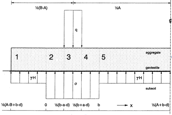
Fig. 1: Stresses and dimensions of a wheel load on a low volume road
Efficacy of geotextiles
The use of geotextiles in road structures is similar to the effect of reinforced concrete. It adds tensile forces to the system. Aggregate alone is incompetent to do so. Geotextiles may be applied in two fashions. They are indicated in literature as “Lateral Restraint” and “Membrane Action”. The first one resembles reinforced concrete the most. Advantages and disadvantages are:
- The aggregate deforms mildly. The road could be paved.
- The vehicle is not bound to a fixed track.
- The improvement of the bearing capacity of the system is limited, since the stiffness of a geotextile is relatively small. By implication, moderate tensile forces are generated.
“Membrane Action” allows a much higher generation of tensile forces. Advantages and disadvantages are:
- The aggregate deforms strongly. The road is better not paved.
- The vehicle is bound to a fixed track, because the geotextile is pre-formed in order to bring in tensile forces.
- The improvement of the bearing capacity of the system is not limited by the stiffness of the geotextile, but by its strength, which is much more effective.
- The geotextile should be anchored well at the sides of the road.
Lateral restraint
Lateral Restraint is a computation, where the aggregate and geotextile interactively work together to balance the wheel load and the bearing capacity of the subsoil. This is often called a SGA system (Soil-Geotextile-Aggregate). Here, the computation will be highlighted and the results illustrated. The original publication is referred to Semmmeijer 1990.
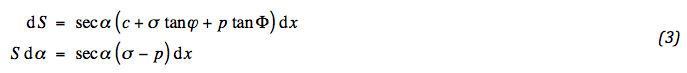
The main idea how stresses are related is sketched for an element in Fig 2. The aggregate and geotextile exchange a mutual normal stress p and shear stress p tan Φ, Φ being the friction angle between soil and geotextile. The aggregate is loaded by the dead soil weight γa H and the surface load q and is deformed by an angle α. Along the faces a normal force N and a shear force T are acting. The geotextile is stretched by a tensile force S while the subsoil reacts by a normal stress σ limited by its bearing capacity, and shear stress c + σ tanϕ; c being the adhesion and ϕ the friction angle, both between subsoil and geotextile. For reasons of simplicity we set the adhesion equal to the cohesion of the subsoil.
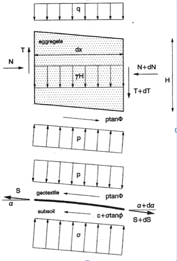
Fig.2: Stresses along road element
The condition of horizontal and vertical equilibrium for both the aggregate and geotextile results in a set of differential equations. For the aggregate:

For the geotextile the conditions become:
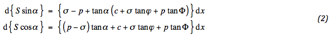
This set can be rearranged by sorting out the derivatives with respect to S and α :
Equilibrium alone however is not sufficient to determine the mechanics of the system. Compatibility must also be included, involving the constitutive behaviour. If G is the shear modulus of the aggregate, which depends on the isotropic and deviatoric stress, the relation between shear force and deflection is,

At this stage there is enough information to work out the derived system of equations. From the first equation of (01) and (04) the stress p can be determined. The result is substituted into (03) and yields two equations, which describe the tensile force and deflection of the geotextile. Besides, substitution of p into the second equation of (01) specifies the normal force N. The result is written out with a few intermediate steps:
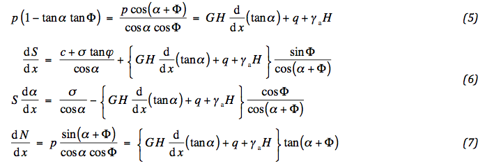
So far the modelling has been very general. This is the right moment to tailor the solution for the special case of small deflections; (06) and (07) may then approximately been written:
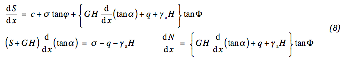
Generally, for moderate to small deformation the parameter GH prevails over the tensile force S, so that the following set of decoupled equations is obtained:

These equations show that the stiffness of the aggregate deals with the deflections, but that the tensile force in the geotextile contributes to the stability by activating a normal force in the aggregate, keeping the mobilized friction below the critical level. The modelling phase is completed now, though not all items are properly specified yet. The concept of mobilized friction and the deformation of the geotextile will be introduced during the solution of the derived equations.
Design
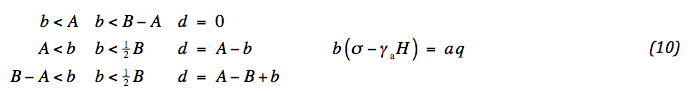
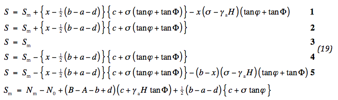
The model can be applied to the actual situation of Fig. 1. B is the effective width of the road; A the track of the vehicle; a the width of the load q; b is the width of the bearing capacity σ and follows from the vertical equilibrium of the subsoil: b ( σ - γ.H ) = n a q. If the aggregate or the track is too small the soil reaction shifts, which is described by the parameter d. The following situations occur,
As shown in Fig. 1, 5 sections with different loading conditions can be distinguished. Sections 1 and 5 do not show deflection, since the soil reaction compensates the dead weight of the aggregate. In sections 2 and 4 the deflection is convex due to the loading q - σ – γ.H; in section 3 concave due to the loading q – σ – γ α H . This can be understood from the second equation of (09).
The procedure of the solution will now be outlined. From the second equation of (09) the deflection is determined. Together with (04) this specifies the shear force T. Also the vertical displacements can be determined. They depend sheerly on the soil parameters and are a criterion for the specification of the required geotextile.
The geotextile comes in to control the mobilized friction. The second equation of (09) is used to determine the course of the normal force, which in its turn is used as a boundary condition to fix the tensile force in the geotextile, defined by the first equation of (09) . The boundary is either the point where the normal force is determined by compatibility, or the edge of the aggregate itself. Once the tensile force is known the condition of compatibility of strain of the geotextile and aggregate specifies a criterion to determine the Young's modulus of the geotextile. Thus the design of the geotextile includes the specification of required stiffness and strength.
Integration of the third equation of (09) to determine the deformation is straightforward. Sections 1 and 5 show no deflection. The remaining sections show piecewise linear deflections which are continuous at the transitions. Maximum deflections appear at the transitions of sections 2 and 3 and 3 and 4. If they are substituted into equation (04) the following maximum shear forces are obtained,

Since dw/dx = tanα, the vertical displacements w can be determined. These are piece-wise quadratic in the sections. The difference in displacement between locations under the wheel and either at the edge or the middle of the aggregate appears to be,

xm is the position under the wheel, where the displacement reaches its maximum. For not too thin height H the vertical displacement appears to be small. This interesting feature will be shown to be related to the quality of the geotextile to be applied.
The next stage of the calculation concerns the normal force in the aggregate. This is determined from the second equation of (09) . It should be noted that the direction of the shear stress at the right of x = xm is opposite to that at the left. That means for x > xm a minus sign must be added. Shear stress can develop only if sufficient displacement is possible. Directly under the wheels this seems questionable. Therefore, it is reasonable to assume that no significant shear stresses occur there. If the maximum normal force is indicated by Nm, then the following expressions are obtained,
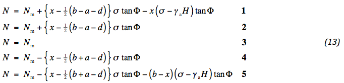
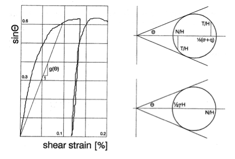
Fig. 3: Mobilized friction
The bold numbers refer to the sections. The value of Nm follows from the extent of mobilized friction. This is determined by the ratio of deviatoric and isotropic stress. There are two points where extreme values may be expected: the edges of the wheel and the edges of the reaction of the subsoil. In the first case the mobilized friction is characterized by an average vertical stress ½ ( σ + q ), a horizontal stress Nm / H and a shear stress Tm / H , in the latter by an average vertical stress ½ γa H and a horizontal one { Nm – ½ ( b - a ± d ) σ tan Φ }. From the Mohr circles in Fig. 3 it can be read:
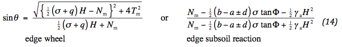
An expression for Nm is obtained by writing Nm explicitly and substitution of (11) . The larger θ is critical, so that the absolute value of d must be applied. The following two alternatives are obtained:
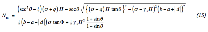
The design must be such that the second value of (15) for the edge of the subsoil reaction is larger than the one for the edge of the wheel. Only then either one of the values of (15) will lead to the maximum mobilized friction specified in (14) . That implies that θ must be chosen large enough. It is noted that by no means the mobilized friction can have values beyond the internal friction of aggregate. Therefore, the loading q cannot be unlimited and should sometimes be decreased to prevent “membrane action“ or even punching.
If the first value of (15) is smaller than the second, then it is determining, implying that the edge of the wheel is critical. This is due to the fact that the role of the normal force is passive and therefore searches for the lowest possible value. An important condition is forced by the discriminant of (15). This reads:

This condition says that the maximal smoothing of the subsoil reaction is proportional with the aggregate height and that a design with d ≠ 0 is less favourable. Extreme values of d will destroy the slab function of the aggregate, leading to punching and large deformations.
Without vehicle there is already a normal force acting in the aggregate due to the dead weight. This force is indicated N0 . It will be specified later. It is possible that the value of N at the sides will decrease below N0 . In that case the activity of the geotextile simply ends from there. By implication, the effective width of the road must be decreased. After a while, the same consideration is true for the tensile force in the geotextile. This affects the middle of the road. Here, we concentrate on the sides. The reduction of the effective width follows from the value of the normal force at the side ½ ( A B + b - d ) of section 1, see Fig. 1 . If appropriate, the width B – A simply can be decreased. It follows from (13) that:

The value of the normal force at the side is:

This completes the second phase of the calculation. Now the attention will be focussed on the geotextile. The tensile force at the side compensates the normal force in the aggregate, if N0 is considered. With the aid of the first equation of (09) the tensile force is determined. Here, the same remark is made with respect to the direction of the friction as for the normal force. Right of x = xm a minus sign must be applied in the differential equation. Furthermore, no shear stress acts direct under the wheels. The result after integration is:
There is a chance that S might vanish before the middle of the track is reached. In that case the same mathematical remedy as before can be applied, now decreasing the track A :

together with (17) this adaptation defines new values of A and B , the original ones are typed bold. It might be necessary to adjust a new value for d according to (10), requiring an iterative procedure.
The last phase of the calculation concerns the compatibility of strain. Directly under the wheels the aggregate is supposed to be in a plastic state. This pushes the aggregate to the sides, stretching the geotextile. The elongation of the geotextile is determined by its axial force:
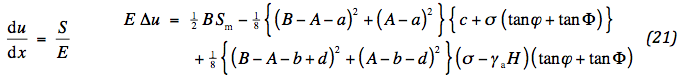
where E is the Young's modulus of the geotextile. Integration is performed by use of (19). For a normative horizontal displacement, the required stiffness is fixed.
The strain in the aggregate only matters at the wheels and at the edges. In between the deformation serves only the bring over friction to the geotextile. According to stress-strain theory the strain of the aggregate depends on the horizontal stress as well as the vertical one, weighted by Poisson's ratio ν. Defining stretching as positive the horizontal strain in the aggregate becomes:

σv is the average vertical stress.
At the edges the axial force in the geotextile will vanish. By implication, the strain in the aggregate will vanish. Therefore it follows from (22), that a fair choice for N0 would be:

Here too, the aggregate stiffness is fixed for a normative horizontal displacement. This value is automatically adjusted by the amount of plasticity. At last a fair choice for the value of N0 must be made. We suppose that this normal force has impeded horizontal strain due to the dead weight. Then it follows by use of (22) :

This is a choice and a subject for future research.
Plastic aggregate behaviour
The previous paragraphs presented a design tool for the geotextile. The influence of the soil is characterized by certain mechanical parameters. A word must be said about the behaviour of one of them, the shear modulus of the aggregate. This modulus depends on the isotropic stress as well as the deviatoric stress.
The shear modulus is proportional with a power of the isotropic stress. Experiments indicate that this power for aggregate material shows values around 0.5, Valstad and Strøm (1976). During the calculation this effect is not taken into account, but it can be fairly well incorporated by utilizing the isotropic stress ½ ( Nm + σH ) in the maximal deflection point as reference.
The shear modulus also depends on the normalised deviatoric stress or mobilized friction, outlined in Fig. 3. The slope of the curve is directly related to the shear modulus. In order to incorporate this behaviour in the design the secant modulus of the curve can be applied. Thus the following shear modulus can be specified:

g(θ) is the secant modulus in Fig. 3; pt is the isotropic stress during the test; β is a non-linearity coefficient, most likely to be 0.5. Gt is the value of the elastic stiffness.
By introduction of the concept of mobilized friction the soil behaviour can be treated as elasto-plastic. By locally approaching (maximum deflection point) the Coulomb strength, the aggregate tends to move sideways. The geotextile then reacts by lateral restraint rather than membrane action to assure equilibrium at the price of moderate displace-ments. The derived model deals with this in a somewhat conservative way. Only at the maximum deflection point the aggregate acts weaker and is elsewhere stiffer. The elongation in the aggregate therefore is underestimated, defining a situation which requires stiffer geotextiles. This is an additional safety and might be a point of future study.
Evaluation
The model is ready and may be applied. It is useful to group the results together. They are copied from: (10), (15), (17), (19), (21), (22) and (24):

At first the normal force is determined. Two expressions are derived. The top one is normative, provided the bottom one does not imply restrictions. This must be checked. In most cases the bottom value exceeds the top one. This is by far sufficient. Next the effective width from the edge is adapted. The tensile force is determined and the effective width in the middle of the road is adapted. At last, the required stiffness of the geotextile is fixed, as well as the adapted stiffness of the aggregate. The bearing capacity is characterised by Brinch Hansen’s rule:

The relation between axle load and traffic stress is mentioned.
Reference
Sellmeijer, J.B., 1990, “Design of Geotextile Reinforced Paved Roads and Parking Areas”, Proceedings of the Fourth International Conference on Geotextiles, Geomembranes and Related Products, Balkema, Vol. 1, The Hague, The Netherlands, pp.177-182.
Valstad, T. and Strøm, E. , “Investigations of the Mechanical Properties of Rockfill for the Svartevann Dam, using Triaxial, Oedometer and Plate Bearing Tests”, Norges Geotek. Inst. , Publ. 110, pp 3-8.