Design of geotextiles applied in unpaved roads - Method Semmmeijer
Use of geotextiles
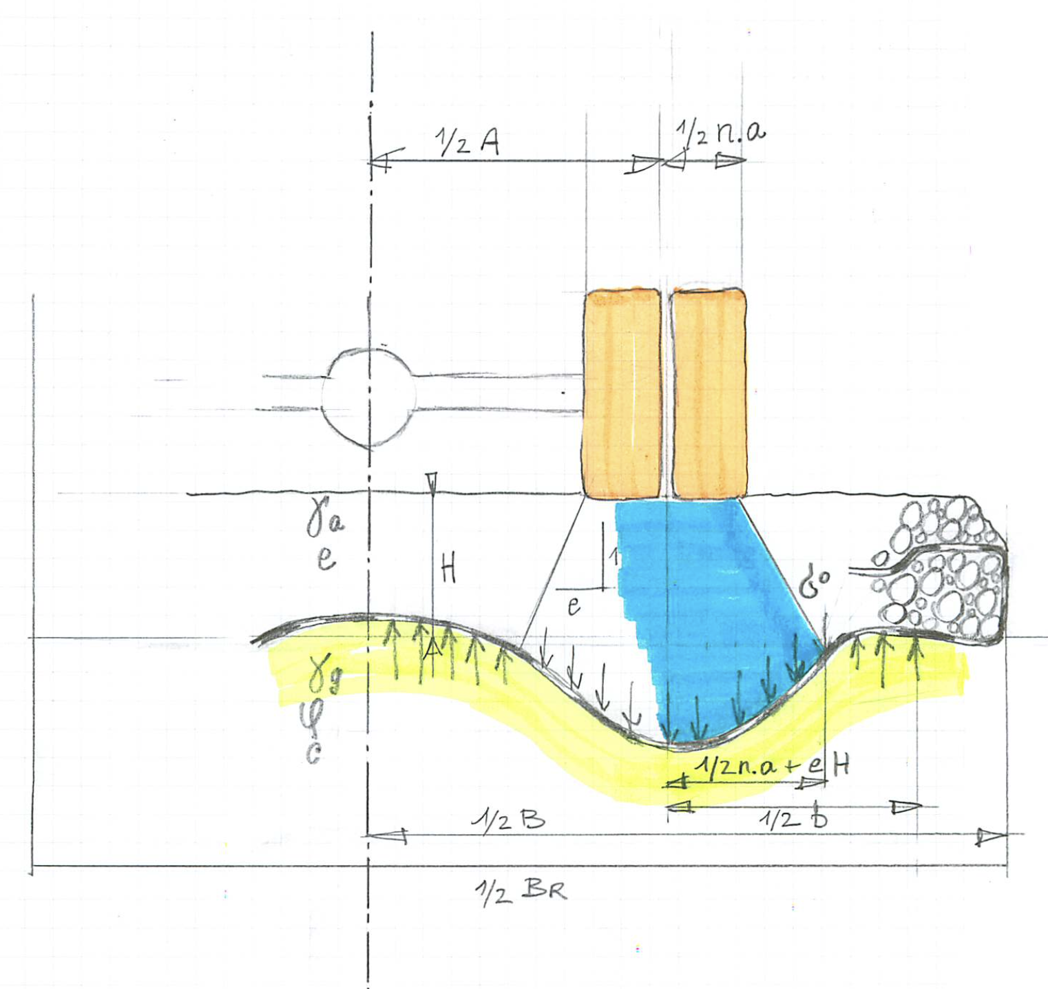
The application of geotextiles (for reinforcement) in road construction is interesting, if the bearing capacity of the subsoil is insufficient. The traffic load impends to collapse together with a part of the road. A geotextile will distribute the load over a wider area of the subsoil, thus, assuring equilibrium. The artwork sketch shows this principle. The traffic load is applied via the wheels of the vehicle. This load distributes in the aggregate, exerting an average stress σ0 at the bottom of the road. The geotextile spreads the load even further to the subsoil, reducing it to σ1 . The design should be such that this last stress meets the bearing capacity of the subsoil.
Efficacy of geotextiles
The use of geotextiles in road structures is similar to the effect of reinforced concrete. It adds tensile forces to the system. Aggregate alone is incompetent to do so. Geotextiles may be applied in two fashions. They are indicated in literature as “Lateral Restraint” and “Membrane Action”. The first one resembles reinforced concrete the most. Advantages and disadvantages are:
- The aggregate deforms mildly. The road could be paved.
- The vehicle is not bound to a fixed track.
- The improvement of the bearing capacity of the system is limited, since the stiffness of a geotextile is relatively small. By implication, moderate tensile forces are generated.
“Membrane Action” allows a much higher generation of tensile forces. Advantages and disadvantages are:
- The aggregate deforms strongly. The road is better not paved.
- The vehicle is bound to a fixed track, because the geotextile is pre-formed in order to bring in tensile forces.
- The improvement of the bearing capacity of the system is not limited by the stiffness of the geotextile, but by its strength, which is much more effective.
- The geotextile should be anchored well at the sides of the road.
Membrane action
Membrane Action is a computation, where a stretched membrane deforms due to vertical stresses. A geotextile is considered to act as a membrane with stresses σ0 and σ1, see artwork sketch. Here, the computation will be highlighted and the results illustrated. The original publication is referred to Semmmeijer et al. 1982.
The membrane action is mainly effective in cross-sectional direction, since the geotextile is anchored at the sides of the road. In longitudinal direction a surplus of slip reduces the effect. Three areas are distinguished: below the wheels and the extensions. The areas are not necessarily symmetrical, as the vehicle might drive too close the middle or the side of the road. They are indexed i: 1, 2, 3.
The deformation is defined by the membrane equation:
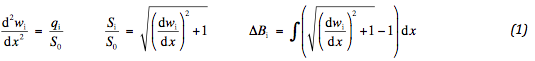
The vertical stress q is the resultant of upper and lower stress on the geotextile. The force S in the geotextile has a constant horizontal component S0. Deformation is indicated by w and the geometrical elongation by ΔB . The distance x is measured from the left side of the subsoil stress. In each area the deformation is determined. Every component has two degrees of freedom. They are specified by the conditions of continuity. The following is found:
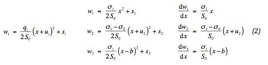
Integration constants ui en si are added. At the far ends no vertical stresses are acting. The values of u1 and u3 are immediately recognised, since the slope of the geotextile vanishes, then. The position of the internal edges are indicated by xℓ and xr . They are specified later. Since deformation and slope at the edges are continuous, we find:
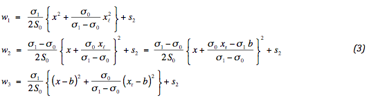
Six conditions were available for the six degrees of freedom. It appears that five are specified. One of the conditions is used to assure vertical equilibrium: (xr - xℓ) σ1 = b σ0 . Therefore, two identical formulations are found for the middle deformation. By implication, no absolute settlement is found. The considered system is in equilibrium at every vertical position. In reality, the highest point of the geotextile is kept in place.
The force in the geotextile fixes the degree of deformation. The bigger this force the smaller the deformation. For compatibility reasons it is important to keep the slope of the geotextile sufficiently small. Consequently, the force in the geotextile is marginally bigger than S0 . The strain of the geotextile and the geometrical elongation are, thus, easily determined. The effect of shear stresses on the geotextile is not considered. Compatibility requires:
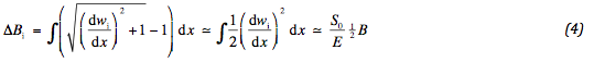
Or, after applying (3):

In this way the force in the geotextile is determined. Adopting vertical equilibrium, we find:

By this condition the deformation differences are fixed. The maximum difference in the middle equals s2 . The difference with the sides amounts:
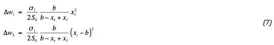
Here too, vertical equilibrium is adopted.
Computation input
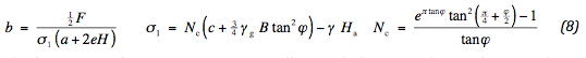
In order to design a geotextile, the required input must be specified. The vertical stress below the geotextile equals the bearing ratio, reduced by the weight of the aggregate. The bearing ratio is characterized by the Brinch Hansen formulae. The width of the reaction stress follows from the axle load and longitudinal stress distribution:
The dimensions of xℓ and xr are geometrically specified. In case of no confining conditions, the load spreads from the location of the wheels and extends to the sides. If, however, the reaction stress extends beyond the middle or side of the road, the stress as a whole shifts inwards or outwards. This leads to:
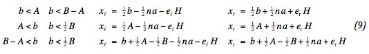
Note, that an index is added to the stress distribution. This distribution is also limited to half the road body. To meet this condition the distribution may be reduced. For verification purposes the sum and difference of xℓ and xr are considered:
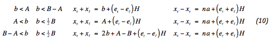
In all cases the difference is equal to total wheel width plus distribution. The middle position matches the position of the wheels, shifted if appropriate.
Reference
Semmmeijer, J.B., Kenter, C.J. and Van Den Berg, C., 1982, “Calculation Method for Fabric Reinforced Road”, Proceedings of the Second International Conference on Geotextiles, IFAI, Vol. 2, Las Vegas, Nevada, USA, August 1982, pp. 393-398.